A Technical Guide from the Engineering Team at Oudeoutdoor
The global outdoor living structures market is expanding rapidly, with aluminum pergolas, carports, and gazebos at the forefront of this growth. The market was valued at USD 6.8 billion in 2025 and is projected to reach USD 12.9 billion by 2033, with pergolas representing the segment expected to witness the highest compound annual growth rate. The outdoor aluminum pergolas market alone is predicted to grow from USD 2,378 million in 2025 to USD 3,035 million by 2031.
But as demand grows, so does the engineering scrutiny these structures face. In markets across North America, Europe, Oceania, and increasingly the Middle East and Southeast Asia, aluminum outdoor structures are no longer treated as decorative afterthoughts. Building codes classify them as permanent structures subject to rigorous wind and snow load requirements. A pergola or carport that fails under environmental loading is not merely a warranty issue—it is a structural failure with serious liability, insurance, and permitting consequences.
At Oudeoutdoor, structural engineering is foundational to our OEM and ODM manufacturing. Every pergola, carport, gazebo, and awning we produce for global export markets is designed with a clear, calculable load path verified against the design standards that govern our clients’ target markets.
This technical guide outlines the core principles of wind and snow load engineering for aluminum outdoor structures. It is written for importers, specifiers, architects, and procurement professionals who need to understand what structural engineering should look like behind the products they source.
1. Why Wind and Snow Load Engineering Matters
1.1 The Shift from Decorative to Structural
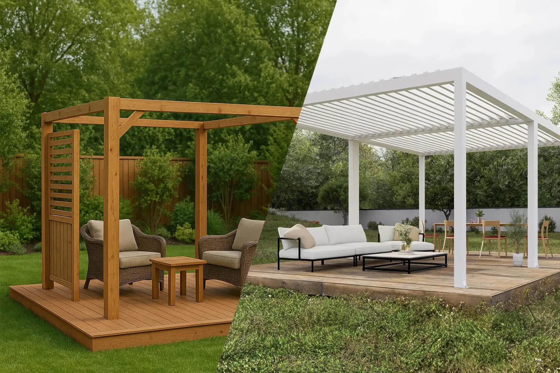
A decade ago, many outdoor structures were treated as lightweight, temporary installations. Today, a louvered aluminum pergola attached to a restaurant facade or a multi-bay carport in a residential development is a permanent architectural element. This shift has significant implications:
- Permitting: Jurisdictions across the United States, Canada, Australia, and Europe increasingly require structural calculations and stamped engineering for permanent outdoor structures exceeding minimum size thresholds.
- Insurance: Structures that fail under wind or snow load can void property insurance coverage if they were not engineered to local code requirements.
- Liability: Commercial installations—hotels, restaurants, resorts—carry elevated liability exposure. A collapse during a weather event has severe legal and reputational consequences.
1.2 The Distinct Engineering Behavior of Open Structures
Aluminum pergolas, carports, and gazebos present unique engineering challenges compared to fully enclosed buildings. Because they have open or semi-open roofs, wind flows over, under, and through the structure, creating complex pressure differentials. The uplift forces—the suction effect generated by wind passing over the roof—can be the dominant load case, often exceeding the self-weight of the structure several times over.
A fundamental engineering concept for outdoor aluminum structures is net uplift: the gross uplift force generated by wind minus the stabilizing dead load of the structure. For lightweight aluminum systems, this net uplift can be substantial, concentrating hundreds of pounds of force on individual post connections and anchors.
Understanding where structures fail is essential. The vast majority of weather-related structural failures in outdoor structures do not originate in the beams or posts themselves. They originate at connections:
- Post-to-footing anchors
- Beam-to-post joints
- Ledger attachments on wall-mounted designs
These connection points define the load path—the continuous route through which environmental forces travel from the roof surface down through the structure and into the foundation. When any link in this load path is undersized or improperly designed, the entire structure is compromised.
2. The Science of Wind Loads on Aluminum Outdoor Structures
2.1 Basic Wind Speed and Design Wind Pressure
Wind load engineering begins with a fundamental distinction: the difference between basic wind speed and design wind pressure.
Basic wind speed refers to the maximum three-second gust speed expected at a specific geographic location, typically measured 33 feet (10 meters) above ground in open terrain. These values are mapped in regional wind speed charts published within national standards.
However, basic wind speed alone is insufficient for structural design. The engineer must convert wind speed into design wind pressure, expressed as force per unit area (e.g., pounds per square foot or kilopascals). This conversion depends on multiple modifying factors defined in structural standards:
- Exposure Category: The roughness of surrounding terrain. Exposure B describes urban or suburban areas with closely spaced obstructions; Exposure D describes flat, unobstructed coastal or open water frontage where wind forces are substantially higher.
- Structure Height: Wind speed increases with elevation above ground. Taller structures experience higher wind pressures.
- Topographic Factor: Hills, ridges, and escarpments can accelerate wind speed locally.
- Gust Effect Factor: Accounts for dynamic amplification of wind loads due to turbulence.
- Pressure Coefficients: The shape, roof slope, and enclosure classification of the structure determine how wind pressure distributes over its surfaces.
These factors collectively convert a geographic wind speed into a specific design wind pressure that governs structural sizing. The methodology is codified in the American Society of Civil Engineers standard ASCE/SEI 7, “Minimum Design Loads and Associated Criteria for Buildings and Other Structures,” which is referenced by the International Building Code (IBC) and adopted across most U.S. jurisdictions, and serves as the definitive reference for wind load determination.
2.2 Uplift: The Critical Load Case
For lightweight aluminum structures, uplift is frequently the governing design condition. The mechanism is straightforward: wind flowing over a roof surface creates a region of negative pressure (suction) above the roof, while pressure may build below. The net effect is an upward force that attempts to lift the entire structure off its foundation.
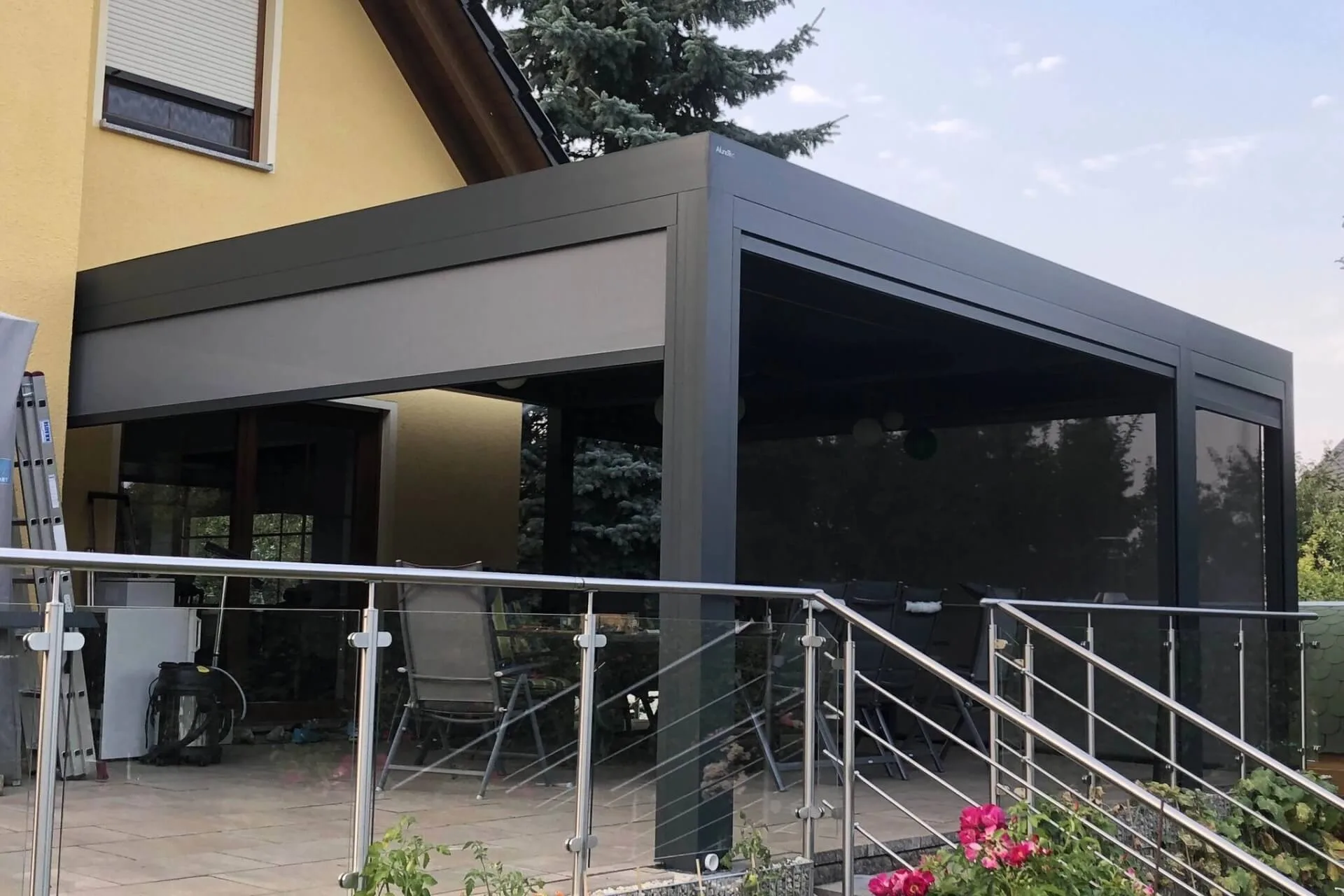
For attached structures like wall-mounted pergolas and canopies, uplift forces are particularly severe. A house wall continuously supports a roof structure; a canopy or pergola attached to that wall is supported only at widely spaced posts concentrated at corners. This creates large tributary areas feeding force into relatively few connection points.
Designing for uplift involves:
- Calculating the gross uplift force per unit area based on design wind pressure and pressure coefficients.
- Subtracting the stabilizing dead load of the structure.
- Distributing the resulting net uplift across the structural frame according to tributary areas.
- Specifying post anchors, base plates, and fasteners capable of resisting the uplift force at each connection with an appropriate safety factor.

2.3 Lateral Wind Resistance
While uplift dominates vertical loading, lateral wind forces push the structure horizontally. This creates bending moments in posts and beams, racking forces at beam-to-post connections, and shear loads at the foundation level.
Lateral resistance is achieved through:
- Post sizing: Larger cross-sections and heavier wall thicknesses increase bending resistance. For high-wind zones, posts of 6×6 inches (150×150 mm) or larger are common, with wall thicknesses selected based on section modulus calculations.
- Moment-resisting connections: Rigid connections between beams and posts, typically achieved with galvanized steel brackets, plates, or proprietary aluminum connectors, transfer bending moments through the joint rather than relying on simple pinned connections.
- Cross-bracing and knee bracing: Diagonal bracing members in one or more bays dramatically increase lateral stiffness and resistance to racking deformation, which is the distortion mode that typically precedes collapse.
- Fixed-base connections: Posts that are rigidly anchored to concrete foundations through cast-in anchor bolts or chemical anchoring systems provide far greater lateral resistance than surface-mounted brackets.
2.4 Regulatory Framework for Wind Design
Different regions govern wind design through different standards. Understanding which framework applies to your market is essential for specifying and sourcing compliant products:
| Region | Primary Standard | Typical Wind Speed Range | Notes |
|---|---|---|---|
| United States | ASCE/SEI 7 (IBC/IRC) | 90–150+ mph | Referenced by International Building Code. Florida Building Code mandates 120–140 mph minimum in hurricane zones |
| Europe | EN 1991-1-4 (Eurocode 1) | Per national annex | Wind actions on structures |
| Australia / New Zealand | AS/NZS 1170.2 | Up to 60 m/s (134 mph) | Part of AS/NZS 1170 structural design actions series- |
| United Kingdom | BS EN 1991-1-4 + UK National Annex | Per national map | British adoption of Eurocode |
| Canada | NBCC (National Building Code) | Per regional tables | References ASCE 7 methodology in part |
Crucially, these standards do not merely prescribe wind speed numbers. They define the complete methodology for determining loads, including exposure classification, topographic effects, internal pressure coefficients, load combinations, and deflection limits. A product “rated for 120 mph wind” only has engineering meaning if the rating references a specific standard and the structural calculations, connections, and anchoring are designed accordingly.
3. Snow Load Engineering: The Vertical Design Challenge
3.1 Understanding Snow Load
Snow load refers to the downward force exerted by accumulated snow on a structure’s roof surface. Unlike wind loads—which are dynamic and multi-directional—snow loads are fundamentally gravitational. However, their engineering complexity arises from substantial regional variability and the interaction between snow accumulation patterns and roof geometry.
Snow load is expressed in force per unit area: typically pounds per square foot (psf) in North America or kilonewtons per square meter (kN/m²) in metric-standard markets.

3.2 Ground Snow Load vs. Roof Snow Load
A critical engineering distinction exists between ground snow load and roof snow load:
- Ground Snow Load (Pg): The snow load measured or statistically determined at ground level for a specific geographic location. This is the reference value published in building code snow load maps.
- Roof Snow Load (Pf): The design snow load applied to the roof surface. The roof snow load is typically a fraction of the ground snow load, because wind scours snow off roofs to some degree. The conversion factor depends on exposure: for wind-exposed roofs, the roof snow load may be 0.6 to 0.7 times the ground snow load; for sheltered roofs, it may be 0.8 times or higher.
3.3 Factors Influencing Snow Load Design
Several factors determine the actual snow load a structure must resist:
- Geographic Location: Snow load requirements vary dramatically by region. In North America, northern states may require ground snow loads of 70 psf (3.35 kN/m²) or more, while southern states may require as little as 5–10 psf (0.24–0.48 kN/m²). Mountainous regions in Europe can require substantially higher loads. This geographic variability means a standard product that works in one market may be structurally inadequate in another.
- Snow Density: Wet, heavy snow can weigh three to four times more per inch of depth than dry, powdery snow. Coastal snowfalls are typically denser than continental snow at similar latitudes.
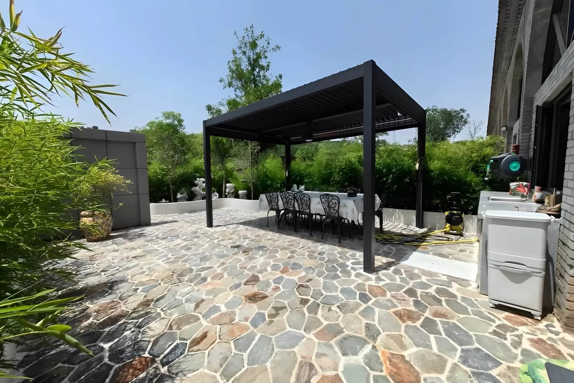
- Roof Pitch: Steeper roofs shed snow more effectively, reducing accumulation. Flat and low-slope roofs—common on modern louvered pergolas and carports—retain snow and therefore require higher load capacity. This is a critical consideration for louvered pergola designs where the roof plane is essentially flat when louvers are closed.
- Drift Loading: Wind-driven snow can accumulate unevenly, creating higher loads in valleys, behind parapets, and at roof level changes-. Drift loading is addressed in Eurocode EN 1991-1-3 through specific load case provisions, and mechanical designers must consider these non-uniform distributions when sizing structural members-.
- Rain-on-Snow Surcharge: In regions where rain frequently falls on accumulated snow, the additional weight of absorbed water can significantly increase loading. This load combination is explicitly addressed in ASCE 7 and EN 1991.
3.4 International Snow Load Standards
| Region | Standard | Reference Snow Load (Typical Range) | Key Provisions |
|---|---|---|---|
| United States | ASCE/SEI 7 Chapter 7 | 5–100+ psf | Ground snow load maps by state; includes drift, rain-on-snow, and unbalanced loading provisions |
| Europe | EN 1991-1-3 (Eurocode 1, Part 1-3) | Varies by national annex | Uniform and drifted snow load cases; applies to altitudes below 1,500 m unless otherwise specified- |
| United Kingdom | BS EN 1991-1-3 + UK NA | Per national map | British adoption of Eurocode snow provisions |
| Australia / New Zealand | AS/NZS 1170.3 | Up to 1.4 kN/m² typical design | Snow load actions; relevant for alpine regions |
| Canada | NBCC | 10–100+ psf | Comprehensive snow load provisions including rain-on-snow |
3.5 Snow Load in Practice: Material and Structural Implications
For aluminum outdoor structures, snow load capacity is primarily a function of:
- Beam and rafter section modulus: The cross-sectional property that determines bending resistance. Deeper sections with thicker walls provide higher section modulus.
- Post buckling capacity: Compression members must resist buckling under axial snow load. Post sizing, wall thickness, and unsupported length all factor into buckling calculations.
- Connection shear capacity: Snow loads transfer through beam-to-post connections as shear forces. These connections must be designed to support the full design load without bearing failure or fastener shear.
- Deflection limits: Codes typically limit live-load deflection to L/240 or L/360 of span, ensuring that snow accumulation does not cause visible sagging or ponding.
Market-specific considerations apply. For example, the Florida Building Code specifies uplift requirements for eaves and cornices at 2.5 times the design uplift wind pressure in Wind Zone I, while cold-climate jurisdictions mandate higher snow load thresholds.
4. Regional Compliance and Design Standards: A Deeper Look
Understanding the geographical scope and application of structural standards is essential for suppliers and buyers in the global market for aluminum outdoor structures.
4.1 North America: ASCE 7 and the IBC
In the United States, the International Building Code (IBC) references ASCE/SEI 7 for minimum design loads. ASCE 7 provides a comprehensive methodology covering dead loads, live loads, snow loads, wind loads, seismic loads, and load combinations. The 2022 edition (ASCE 7-22) represents the current standard at the time of writing.
Key wind design provisions include:
- Multiple analysis methods: Directional Procedure (Chapter 27), Envelope Procedure (Chapter 28), and Wind Tunnel Procedure (Chapter 31) for complex geometries.
- Exposure categories B, C, and D governing terrain roughness and resulting wind pressure.
- Enclosure classifications: enclosed, partially enclosed, partially open, and open—each with different internal pressure coefficients that significantly affect net loading.
- Component and Cladding (C&C) provisions for design of individual structural elements and connections.
In hurricane-prone regions, additional requirements apply. The Florida Building Code mandates wind resistance of at least 120–140 mph for carport-type structures in high-velocity hurricane zones (HVHZ). Miami-Dade County’s Notice of Acceptance (NOA) program is widely recognized as the most stringent product approval process for exterior building components in the United States, certifying products for wind speeds up to 190 mph.
4.2 Europe: The Eurocode System
In Europe, structural design for aluminum outdoor structures falls under the Eurocode framework:
- EN 1990: Basis of structural design (load combinations, safety factors)
- EN 1991-1-4: Wind actions
- EN 1991-1-3: Snow loads-
- EN 1999: Design of aluminum structures (material properties, member design, connection design)
Each EU member state publishes a National Annex that specifies nationally determined parameters including wind speed maps, snow load maps, and partial safety factors. A structure designed for Germany may require different load parameters than one designed for Spain, even though both reference the same Eurocode.
4.3 Australia and New Zealand: AS/NZS 1170
The AS/NZS 1170 series covers structural design actions:
- AS/NZS 1170.2: Wind actions
- AS/NZS 1170.3: Snow and ice actions
Typical design parameters for aluminum structures in this region include wind speeds up to 60 m/s (approximately 134 mph) and snow loads up to 1.4 kN/m²-. Structures designed to AS/NZS 1170 must also address the specific wind regions defined in Australian and New Zealand wind hazard maps.
4.4 The Importance of Regional Adaptation
A product engineered for one market is rarely adequate for another without structural re-evaluation. A pergola designed for 90 mph wind speeds in an inland U.S. location would be severely under-designed for a coastal Florida installation requiring 150 mph certification. Similarly, a structure designed for European snow loads in Milan (low snow zone) would be inadequate for alpine regions requiring substantially higher capacity.
This regional variability is why Oudeoutdoor’s OEM and ODM engineering process begins with your specific target market requirements. We do not sell one-size-fits-all structures; we engineer to the standards that govern installation.
5. Structural Testing, Certification, and Quality Validation
Engineering calculations must be validated by physical testing, particularly for products destined for regulated markets where permitting requires third-party evidence.
5.1 Wind Load Testing
Wind load testing subjects full-scale structural assemblies or representative components to simulated wind pressures. Test protocols include:
- ASTM E330: Standard test method for structural performance of exterior windows, doors, skylights, and curtain walls by uniform static air pressure difference—frequently adapted for testing pergola and carport roof panels and assemblies-.
- ASCE/SEI 49: Wind tunnel testing for buildings and other structures, providing minimum requirements for conducting and interpreting wind tunnel tests to determine wind loads on structural components and cladding-.
- Manufacturer-specific protocols: Leading pergola manufacturers conduct full-scale structural testing with third-party agencies such as Intertek, subjecting complete assemblies to wind speeds equivalent to Category 3 hurricanes (167 km/h or higher) with documented pass criteria of no structural damage and no deformation.
5.2 Snow Load Testing
Snow load testing typically involves static load application to the roof structure. Weights are incrementally applied to simulate snow accumulation, with deflection measured at each stage. A well-designed structure will demonstrate:
- Linear deflection behavior within the design load range.
- Full elastic recovery after load removal, with residual deflection measured in millimeters.
- No yielding, local buckling, or connection distress at the design load.
Intertek-certified snow load testing on aluminum pergola structures has documented elastic recovery within 2 mm of original geometry after application of 204 kg/m², equivalent to approximately 40 cm of heavy wet snow.

5.3 Material Verification
Structural performance begins with material quality. For aluminum outdoor structures, key material standards include:
- ASTM B221: Standard specification for aluminum and aluminum-alloy extruded bars, rods, wire, profiles, and tubes-.
- ASTM B209: Standard specification for aluminum and aluminum-alloy sheet and plate.
- EN 755: Extruded aluminum alloy profiles—mechanical properties, tolerances.
- EN 1090: Execution of steel and aluminum structures, establishing requirements for structural fabrication quality.
At Oudeoutdoor, all incoming aluminum profiles undergo material certification verification—confirming alloy grade (typically 6063-T5 or 6061-T6 for structural applications), temper, and mechanical properties against mill certificates and applicable standards.
6. Connection Design: Where Theory Meets Practice
6.1 The Load Path Principle
The most elegantly sized beams and posts are irrelevant if the connections between them cannot reliably transfer design loads. Structural failures in outdoor aluminum structures overwhelmingly initiate at connections, not in the members themselves.
The load path for a typical freestanding aluminum pergola under wind and snow loading follows this sequence:
- Roof surface (louvered panels, polycarbonate sheets, or fabric membrane) receives wind pressure/suction and snow weight.
- Rafters or purlins collect these distributed loads and transfer them to beams.
- Beams transfer reactions to posts through beam-to-post connections.
- Posts carry axial compression (snow + dead load), bending moment (wind), and shear (lateral wind) down to the base.
- Base connections transfer all forces into the foundation or anchoring system.
Every component in this chain must be sized for the load it receives. If a base plate is adequately anchored but beam-to-post connections are undersized, the structure fails at the beam-to-post joint. If the post is robustly sized but the foundation is inadequate, the structure overturns. A properly engineered structure has a continuous, balanced load path from top to bottom.

6.2 Connection Types in Aluminum Structures
Beam-to-Post Connections
These are typically the most structurally demanding connections in a pergola or carport. They must simultaneously resist: shear from vertical loads (snow, self-weight), moment from lateral wind pressure on the post, and tension from wind uplift. Common connection approaches include:
- Bolted bracket connections: Galvanized or stainless steel angle brackets, T-plates, or custom-fabricated connectors bolted to both beam and post. These provide positive mechanical engagement and can be engineered for specific design loads.
- Proprietary aluminum connectors: Extruded aluminum connectors designed to mate with specific profile geometries, providing clean aesthetics and consistent structural performance.
- Through-bolt connections: For deeper sections, through-bolts with backing plates distribute bearing stresses over larger areas, reducing the risk of localized aluminum yielding.
Base Connections and Anchoring
The post-to-foundation connection is the single most critical element in resisting uplift. Engineering approaches depend on foundation type:
- Cast-in-place anchor bolts: Bolts set into wet concrete during foundation pouring provide the highest uplift capacity when properly specified, with embedment depth, bolt diameter, and edge distance calculated per design load.
- Post-installed (chemical or expansion) anchors: Used when anchoring to existing concrete. Epoxy-based chemical anchors provide excellent pullout resistance in cracked and uncracked concrete.
- Surface-mounted base plates: When anchoring to existing paved surfaces, larger base plates with multiple anchor points distribute uplift forces, though capacity is limited by the strength of the substrate.
The engineering principle is clear: simply placing posts on patio pavers or using shallow concrete footings is inadequate for all but the lowest wind zones. For hurricane-resistant structures, anchors must be sized for the full design uplift force and embedded to sufficient depth for the substrate conditions.

6.3 Cross-Bracing and Lateral Stability
In addition to moment-resisting connections, cross-bracing in one or more structural bays dramatically improves lateral performance. Diagonal bracing members—whether tension rods, cables, or profiled struts—create triangulated sub-frames that resist racking deformation. Even a small amount of bracing can substantially increase overall lateral stiffness and the structure’s ability to survive high-wind events.
7. Oudeoutdoor’s Engineering Approach: Designed for Compliance from the Start
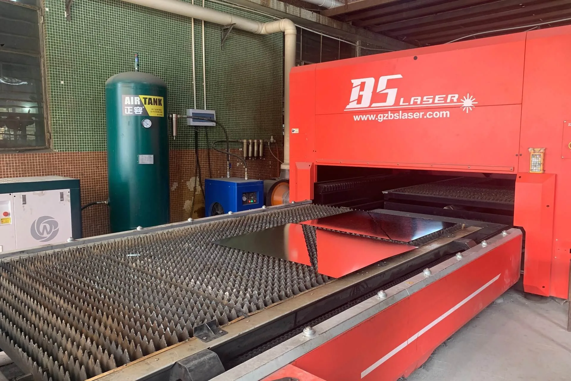
At Oudeoutdoor, we integrate structural engineering into every stage of the OEM/ODM manufacturing process. Our approach is designed to ensure that products leaving our Foshan factory are structurally validated for their intended markets.
7.1 Design-Phase Engineering
Every project begins with a clear definition of structural requirements: target market, applicable standards, required wind speed rating, snow load capacity, and any regional code amendments. Our engineering team then performs preliminary structural analysis to validate member sizing, connection design, and anchoring recommendations before manufacturing begins.
7.2 Profile Selection and Optimization
Not all aluminum extrusions are structurally equivalent. We select profiles based on section properties—moment of inertia, section modulus, and radius of gyration—that directly determine bending resistance, deflection under load, and buckling capacity. For structural members, we specify 6063-T5 or 6061-T6 aluminum alloy, grades that offer the established strength, extrudability, and corrosion resistance suitable for outdoor structural applications.
7.3 Connection System Engineering
Our engineering team designs and specifies connections for each product configuration, ensuring that the complete load path—from roof surface to foundation—is continuous, calculable, and compliant. For OEM projects, we can engineer to your proprietary connection system or adapt your designs for structural compliance in your target market.
7.4 Quality Verification
Structural quality is verified throughout production. In-process inspections confirm profile dimensions, wall thicknesses, weld quality (where applicable), fastener specifications, and assembly tolerances. We support third-party inspection and testing per client requirements.
7.5 Documentation for Permitting
For projects requiring building permit submission, we provide structural calculations, material certifications, and technical documentation formatted for review by local building officials. This documentation package supports our clients in streamlining their permitting processes.
8. Practical Guidance for Importers and Specifiers
8.1 Questions to Ask Your Manufacturer
When sourcing aluminum outdoor structures for wind and snow load compliance, the following questions are essential:
- Which specific structural standard was used for design? “Meets building code” is insufficient. The manufacturer should reference a specific standard: ASCE 7-22, EN 1991-1-4, AS/NZS 1170.2, etc.
- What is the design wind speed and to which exposure category? Wind speed without exposure category is meaningless. A structure rated for 120 mph in Exposure B may not be adequate for 120 mph in Exposure D.
- What is the design snow load? The answer should be in psf or kN/m², not inches of snow depth, because snow density varies.
- Have the connections been engineered for uplift? The post-to-foundation connection is the critical element. Ask for anchor specifications.
- Are structural calculations available? A professional manufacturer should be able to provide calculations stamped by a qualified engineer for permit submission.
- Has the structure been tested? Independent third-party testing (Intertek, SGS, ICC-ES) provides validation that engineering calculations translate to real-world performance.
8.2 Common Pitfalls in Structural Specifications
- Confusing wind speed with wind pressure: A structure might survive a 100 mph gust but fail under sustained wind that generates continually repeated suction cycles. Fatigue matters.
- Ignoring exposure category: A pergola in a sheltered suburban backyard experiences fundamentally different wind loading than the same pergola on a coastal restaurant patio. The engineering must reflect the actual site conditions.
- Underestimating snow density: 12 inches of dry powder and 12 inches of wet coastal snow are entirely different loads. Designing to snow depth rather than snow weight is a fundamental error.
- Neglecting drift and unbalanced loading: Snow rarely accumulates uniformly. Drift loading can concentrate loads in ways that induce local failures even when the average load is within capacity.
- Assuming product ratings are transferable: A product certified for one market is not automatically compliant in another. Florida Building Code certification does not imply compliance with European Eurocodes, and vice versa.
Conclusion: Engineering Is the Foundation of Trust
In the international trade of aluminum outdoor structures, structural engineering separates commodity suppliers from manufacturing partners. A pergola or carport that performs beautifully on a calm, sunny day but fails under a winter snowstorm or a coastal squall represents a failure not of material but of engineering.
At Oudeoutdoor, we believe that structural integrity is a prerequisite, not an upgrade. Every product we manufacture—whether an OEM design built to client specifications or an ODM solution adapted from our catalog—is engineered with a defined, calculable load path verified against the standards governing the target market. We do not sell structures that “should be fine.” We engineer structures we can stand behind—with calculations, certifications, and testing to prove it.
This commitment to engineering rigor is what our global import partners rely on, and it is the foundation upon which we build lasting commercial relationships.
Contact Oudeoutdoor’s engineering team to discuss your structural requirements for aluminum pergolas, carports, gazebos, and outdoor structures.
Note: This technical guide provides an overview of wind and snow load engineering principles relevant to aluminum outdoor structures. For project-specific structural design, always consult a licensed professional engineer familiar with local building codes and site conditions.