You’ve chosen the structure, finalized the dimensions, and placed the order. Now comes the part that determines whether the project goes smoothly or becomes a frustrating series of delays: site preparation.
Aluminum pergolas, carports, and canopies are engineered products, and like any engineered system, they perform only as well as the foundation they sit on. A perfectly manufactured structure installed on an undersized footing will fail—not because of the product, but because the load path was broken before installation even began.
This guide walks through the site preparation and installation planning process for commercial aluminum structures. Whether you’re a contractor preparing a bid or a property owner trying to understand what’s involved, the information here will help you avoid the most common installation mistakes.
1. Start with the Engineering, Not the Digging
Before any equipment arrives on site, you need to know what the structure demands from the ground. The starting point is the structural engineering package—the set of calculations and drawings that define post sizes, connection details, and, critically, the reactions at each support point.
We’ve covered the engineering principles in depth in Understanding Wind and Snow Load Engineering for Commercial Aluminum Structures. The key number to extract from the engineering package is the uplift force at each post base. Wind passing over the roof creates suction that tries to lift the structure off the ground. In many locations, this uplift force exceeds the weight of the structure several times over. Your foundation and anchoring system must resist that force with a proper safety factor.
For projects in the United States, the governing standard is typically ASCE 7, referenced by the International Building Code. For Europe, it’s EN 1991. For Australia and New Zealand, AS/NZS 1170. If your manufacturer cannot provide calculations that reference one of these standards, you’re taking a significant risk.
The engineering package should also specify:
- Post base reactions: Vertical, horizontal, and moment forces at each support.
- Anchor bolt requirements: Diameter, embedment depth, grade, and edge distance.
- Foundation size and reinforcement: Based on soil bearing capacity and uplift resistance.
- Connection details: How posts attach to the base plate, and how the base plate attaches to the foundation.
At Oude Outdoor, we provide this documentation as part of every commercial order. Our engineering team works in ASCE 7 and EN 1991 daily, and we can supply stamped calculations for permit submission when required.
2. Foundation Types: Choosing the Right Base
The foundation is where site conditions meet structural requirements. The right choice depends on the structure type, local soil, frost depth, and whether the installation is on grade, elevated, or attached to an existing building.
2.1 Cast-in-Place Concrete Footings
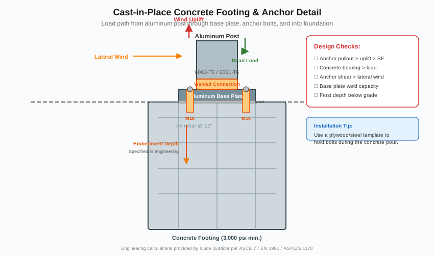
For freestanding pergolas and carports, cast-in-place concrete footings are the most reliable and common foundation solution. Anchor bolts are set into the wet concrete during pouring, providing a direct load path from the post base into the foundation.
Key considerations:
- Footing depth: Must extend below the local frost line to prevent frost heave from lifting the footing and damaging the structure above. In northern U.S. states, this can mean 36 to 48 inches (900–1200 mm) below grade. In warmer climates, 24 to 30 inches (600–750 mm) may suffice.
- Footing diameter: Typically 18 to 24 inches (450–600 mm) for a standard pergola post, but larger structures with longer spans or higher wind loads require larger footings. The engineering calculations will specify the exact dimensions.
- Anchor bolt placement: Must be accurate to within ±1/8 inch (3 mm). A misaligned bolt can prevent the base plate from seating properly. The best practice is to use a wooden or steel template that holds the bolts in position during the pour.
- Concrete strength: 3,000 psi (20 MPa) minimum for most applications. Higher strength may be specified for heavy structures or aggressive environments.
2.2 Post-Installed Anchors (Existing Concrete)
When attaching to an existing concrete slab or deck, you’ll use post-installed anchors. These fall into two categories:
- Epoxy (chemical) anchors: A two-part adhesive is injected into a drilled hole, then a threaded rod is inserted. Once cured, the anchor provides excellent pullout resistance in both cracked and uncracked concrete. Epoxy anchors are the preferred choice for most commercial installations because they’re less likely to crack the concrete during installation.
- Expansion anchors: A mechanical wedge expands against the hole walls when tightened. They’re fast to install but can create stress concentrations that lead to cracking in thinner slabs or near edges. We generally recommend epoxy anchors for structural applications.
The critical specification for post-installed anchors is embedment depth. A shallow anchor will pull out under uplift before the structure reaches its design capacity. The engineering package should specify the exact depth required for your anchor type and concrete strength.
2.3 Elevated Decks and Rooftops
For rooftop bars and terraces, the structure is often installed on an existing structural slab or steel deck. In these situations, the anchor points must be coordinated with the building’s structural engineer to ensure that the loads can be transferred safely through the existing structure.
This is where aluminum’s light weight becomes a major advantage. Aluminum structures weigh roughly one-third as much as equivalent steel, which often means the existing roof structure can support the new loads without reinforcement. We covered this weight advantage in Aluminum vs. Wood Pergolas: The Ultimate ROI Guide.
For rooftop installations, we typically recommend:
- Through-bolting to the structural slab where possible, using backing plates below the deck.
- Epoxy anchors where through-bolting isn’t feasible, with specified embedment depths.
- A continuous structural connection to the building frame for large structures, rather than isolated point anchors.
2.4 Attached (Wall-Mounted) Structures
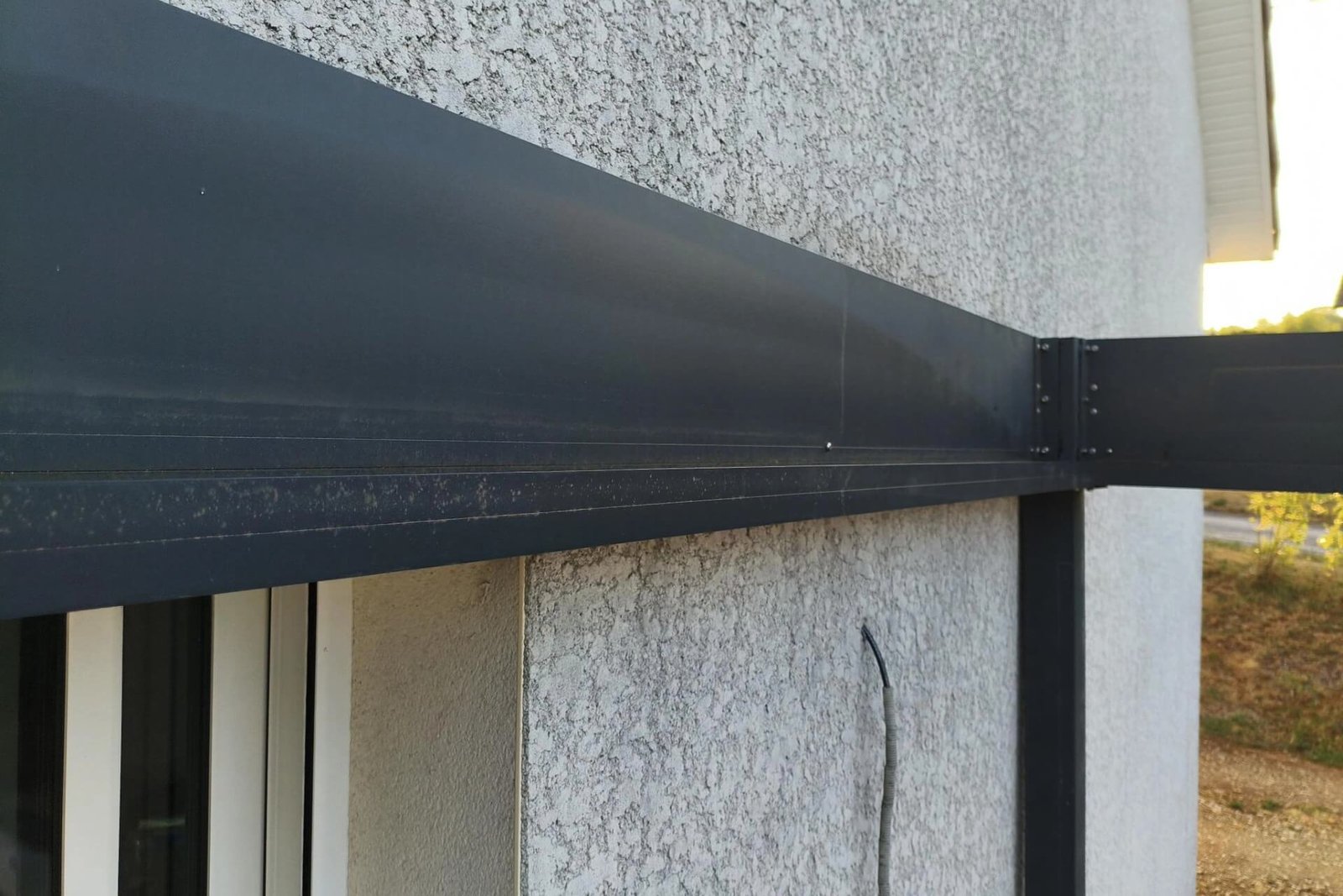
Wall-mounted pergolas and canopies attach to an existing building wall on one side. The ledger connection is just as critical as the post foundations on the other side—if the ledger fails, the structure pivots outward and collapses.
The ledger must be secured to structural framing within the wall—studs, beams, or concrete—not to surface cladding or veneer. The connection details will depend on the wall construction:
- Wood-framed walls: Ledger bolts or lag screws sized for the uplift and shear loads, with washers large enough to prevent pull-through.
- Concrete or masonry walls: Expansion or epoxy anchors, or through-bolts where access to both sides is available.
- Steel-framed walls: Bolted connections to the structural steel, with appropriate corrosion protection.
Proper flashing is essential to prevent water intrusion at the ledger. The structure’s integrated drainage system should discharge water away from the wall, not behind it. This is a detail that separates professional installations from problematic ones.
3. Anchoring and Load Transfer: The Details That Matter
3.1 Base Plate Design
The aluminum post connects to the foundation through a base plate, typically a welded or bolted aluminum or steel plate. The plate distributes the post’s axial load, bending moment, and shear force across the foundation surface.
The base plate must be sized so that the anchor bolts have enough spacing to resist the overturning moment without exceeding the concrete’s bearing capacity. The engineering drawings will specify the plate dimensions, bolt pattern, and required weld or fastener sizes.
3.2 Leveling and Shimming
Aluminum structures are precision-engineered, and small misalignments compound across the frame. Posts must be plumb and level within tight tolerances. Shims—thin metal or plastic plates—are used to level the base plate before final tightening.
We recommend using structural shims that are corrosion-resistant and sized to fill the entire base plate area, not just small points. Point loading on shims can create stress concentrations that crack the concrete or deform the plate.
3.3 Grouting
After leveling, the gap between the base plate and the concrete should be filled with non-shrink grout. This creates a uniform bearing surface and prevents water from pooling under the plate, which can lead to corrosion and freeze-thaw damage in cold climates.
Grouting is often skipped in residential installations but should be standard practice for commercial projects. It’s a small step that significantly extends the life of the anchoring system.
4. Drainage and Site Grading
Aluminum structures with louvered roofs capture rainwater when the louvers are closed and channel it through concealed drainage systems. That water has to go somewhere.
For ground-level installations, ensure that:
- The structure is placed on a slight grade or that drainage inlets are positioned to carry water away from the foundation.
- Downspout discharge points don’t erode the soil around footings. A splash block or drainage pipe may be needed.
- If the structure sits on a paved surface, the surface has adequate slope to prevent ponding.
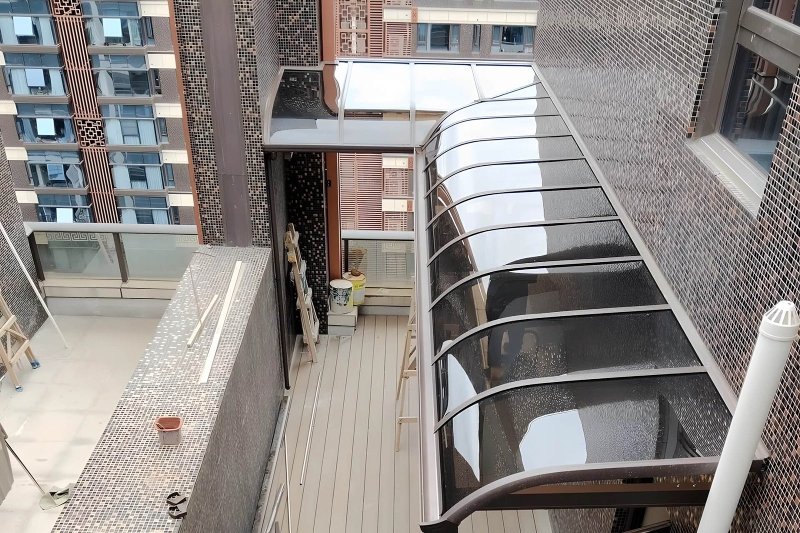
For rooftop installations, the drainage must connect to the building’s existing roof drainage system. The structural posts often serve as the downspouts, with water discharging through the roof deck into the building’s internal drainage. This coordination with the building’s mechanical engineer is essential.
Our product pages describe the integrated drainage systems in more detail for each category: aluminum pergolas, carports, and canopies.
5. Electrical and Smart Feature Preparation
If your structure includes motorized louvers, LED lighting, heating, or sensors, electrical planning must happen during site preparation, not after the structure is up.
What to prepare:
- Power supply: Most motorized louver systems run on 24V DC, with a transformer converting from standard 110–240V AC. The transformer needs a protected location—either inside the structure’s post or in a nearby weatherproof enclosure.
- Conduit runs: Wiring for lighting and controls should be routed through the structure’s hollow profiles wherever possible, with conduits sized for the anticipated load. Plan conduit locations before pouring concrete.
- Control wiring: If wall-mounted control panels are specified, pre-wire the locations before finishing interior spaces.
- Smart system integration: If the structure will connect to a building automation system or smart home hub, confirm compatibility during the design phase, not during installation.
The integration of smart features is discussed in our market analysis article: Why Bioclimatic Pergolas are Dominating the 2026 Outdoor Architecture Market.
6. Installation Sequencing and Timelines
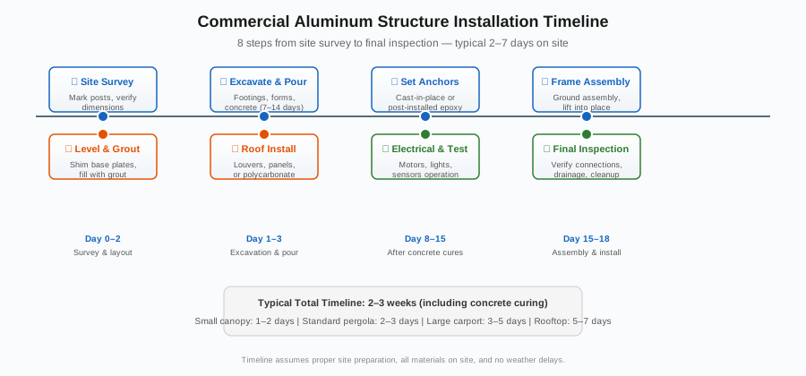
A typical commercial installation follows this sequence:
- Site survey and layout: Mark post locations, verify dimensions, and confirm that underground utilities are clear.
- Excavation and footings: Dig holes, set forms, and pour concrete. Allow 7–14 days for concrete to reach sufficient strength before loading.
- Anchor setting: For cast-in-place anchors, this happens during the pour. For post-installed anchors, drill and set after the concrete has cured.
- Frame assembly: Assemble the structure on the ground where possible, then lift into place. For large structures, a crane may be required.
- Post alignment and grouting: Level, shim, and grout the base plates.
- Roof installation: Install louvers, panels, or polycarbonate sheets.
- Electrical and controls: Connect motors, lighting, and sensors; test operation.
- Final inspection and cleanup: Verify all connections, check drainage, and clean the structure.
Typical timelines:
- Small canopy: 1–2 days
- Standard pergola: 2–3 days
- Large carport or multi-bay structure: 3–5 days
- Rooftop installation with crane access: 5–7 days
These timelines assume the site is properly prepared and all materials are on site. The most common cause of installation delays is inadequate foundation preparation—either the footings were poured wrong, the anchors are misaligned, or the electrical wasn’t ready.
If you’re looking for guidance on planning the entire sourcing process from design to delivery, our guide to planning and sourcing custom aluminum structures covers the full journey in one place.
7. Common Installation Mistakes to Avoid
7.1 Skipping the Engineering Review
Some contractors assume that a standard anchor bolt pattern will work for any structure. It won’t. The anchor specification depends on the structure’s calculated uplift and shear reactions. Using a generic anchor because “it’s worked before” is a gamble you don’t want to take on a commercial project.
7.2 Pouring Footings Without a Template
Misaligned anchor bolts are the most frequent installation error we see. Once the concrete has cured, correcting a misplaced bolt requires core drilling, epoxy anchors, or—worst case—demolition and re-pour. A simple plywood or steel template costs almost nothing and eliminates this risk.
7.3 Ignoring Frost Depth
In cold climates, a footing that doesn’t extend below the frost line will heave upward when the ground freezes, cracking the structure and pulling anchors out of the concrete. The engineering package should specify the required depth, but the local building official will have the final say.
7.4 Inadequate Waterproofing at Attachments
Wall-mounted structures need proper flashing to prevent water intrusion. If the flashing fails, water seeps behind the ledger, causing rot in wood-framed walls or corrosion in steel framing. The damage may not appear for years, but it’s expensive when it does.
7.5 Overlooking the Electrical Rough-In
Running electrical conduit after the structure is assembled is far more difficult than doing it during the frame assembly. If your structure will include lighting, heating, or motorization, plan the wiring routes in advance and coordinate with your electrician before installation begins.
8. Working with Your Manufacturer During Installation
The best manufacturers don’t just ship a product—they support the installation process. At Oude Outdoor, our engineering team stays available throughout the installation:
- Pre-installation review: We’ll walk through the engineering drawings with your installer to confirm that everyone understands the load path, anchor requirements, and assembly sequence.
- Video support: If your team encounters an issue on site, we’ll get on a video call to troubleshoot in real time.
- Documentation: Every order ships with illustrated assembly manuals in your preferred language, including detailed foundation and anchoring drawings.
- Spare parts: We recommend ordering a small spare parts kit with every container, including extra fasteners, shims, and touch-up paint. It’s a minor cost that prevents major delays.
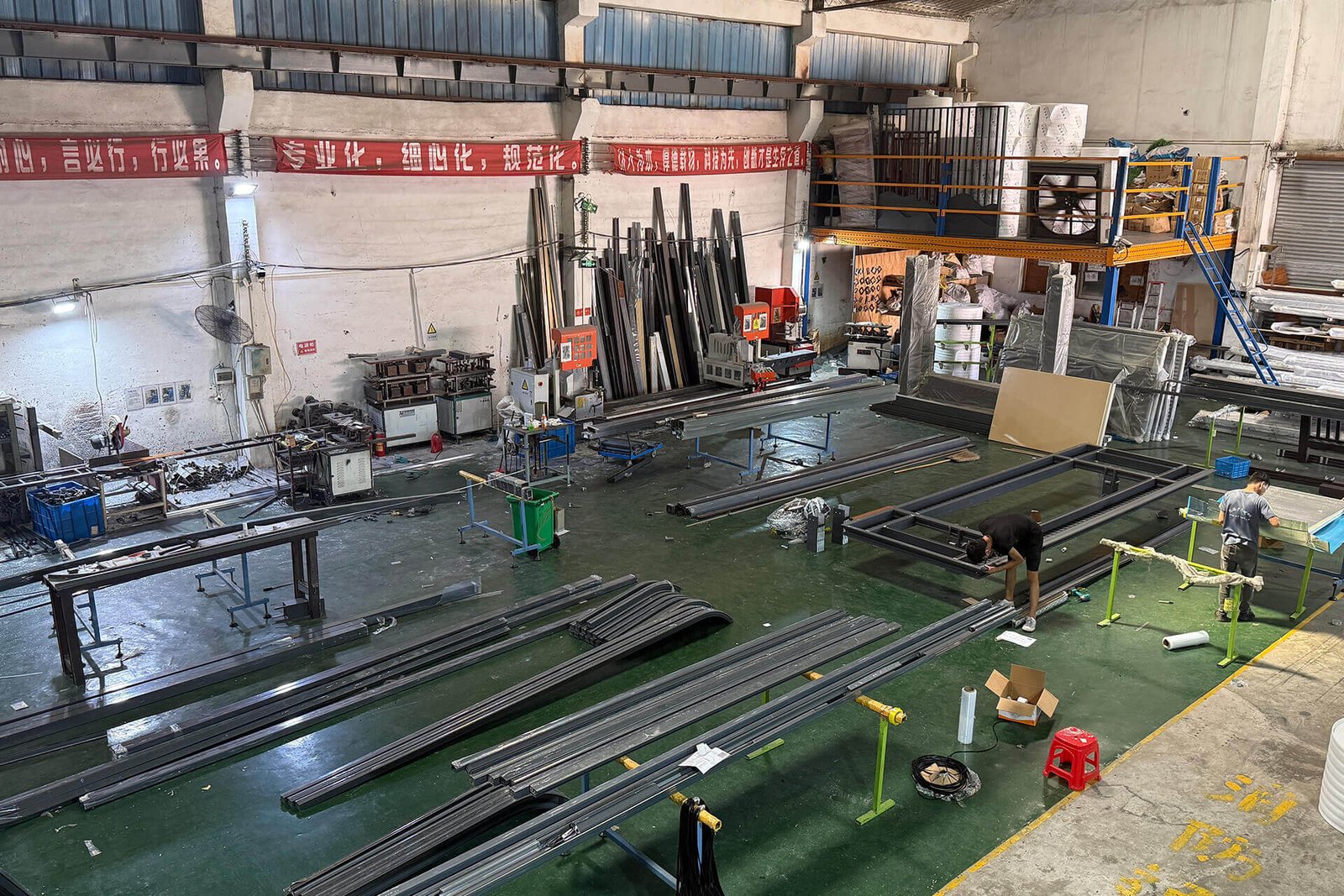
Our 15,000-square-meter factory in Foshan is designed to support these details—CNC-cut profiles that match the drawings exactly, and packaging that protects components so they arrive ready to install.
9. Conclusion: Preparation Prevents Problems
Site preparation is not the most exciting part of an outdoor structure project, but it’s the part that determines whether the finished product looks and performs the way it should. A well-prepared site—proper footings, accurate anchors, and ready utilities—makes the installation fast, clean, and trouble-free. A poorly prepared site turns even the best-engineered structure into a source of frustration.
Before your structure ships, take the time to:
- Review the engineering package and understand the foundation and anchor requirements.
- Verify site conditions—soil type, frost depth, existing utilities, and drainage.
- Prepare the electrical rough-in for any motorized or illuminated features.
- Coordinate with your installer on sequencing, equipment access, and timeline.
- Confirm that your manufacturer provides ongoing support during installation.
At Oude Outdoor, we’re committed to supporting our customers from the first design consultation through the final bolt tightening. If you’re planning a commercial aluminum structure, our team can help you evaluate your site conditions and prepare the technical documentation your installer needs.
Contact Oudeoutdoor today with your project details—dimensions, site conditions, and intended use—and we’ll provide a feasibility assessment, transparent quotation, and the engineering support to get your site ready.